Personal LaserWriter 300 recap · Nov 2026 Recapping the controller board in my Personal LaserWriter 300.
My Personal LaserWriter 300 was completely dead. I’d plug it in, turn it on, and get nothing at all, no lights and no sounds.
The problem was the controller board, which  Apple’s service manual calls the controller assembly. It runs the print engine, and the power supply is on it too. Like a lot of 30-year-old electronics, a few of its electrolytic capacitors had leaked, and the electrolyte had corroded the copper around the chip that starts the power supply. I replaced every electrolytic cap on the board, cleaned up the corrosion, and it started right up.
I couldn’t find a recap guide for this printer anywhere, so here’s what I did. I worked through the diagnosis with Claude, and it put together the cap list below from the values I read off the old ones.
That manual covers the Personal LaserWriter 300, the 320 and the LaserWriter 4/600 PS together, so this might help with those too. Every cap’s position and value is printed on the board, so check yours against my list before you order anything.
The board runs on mains voltage, and its big capacitor can hold a dangerous charge after you unplug the printer. Before you touch the board, unplug the printer, measure across the big 330µF capacitor (C210) and wait until it reads close to zero. Check it again every time you come back to the board.
What you need
Parts
- 25 capacitors, about $13 in
 this Digi-Key cart (the list is in step 4)
- 99% isopropyl alcohol
- Dish soap and distilled water
- UV-cure solder mask, if you end up scraping any traces
Tools
- A multimeter
- A soldering iron (I used my
 Pinecil)
- Solder wick
- An X-Acto knife
- A UV light
- Compressed air
1. Find the problem
I took the printer apart and got the board out by following the Take Apart chapter of Apple’s service manual.
Then test both fuses, FU101 and FU201, next to the CAUTION label. Use your meter’s continuity setting rather than going by how they look. Mine were both fine, so the problem was further in.
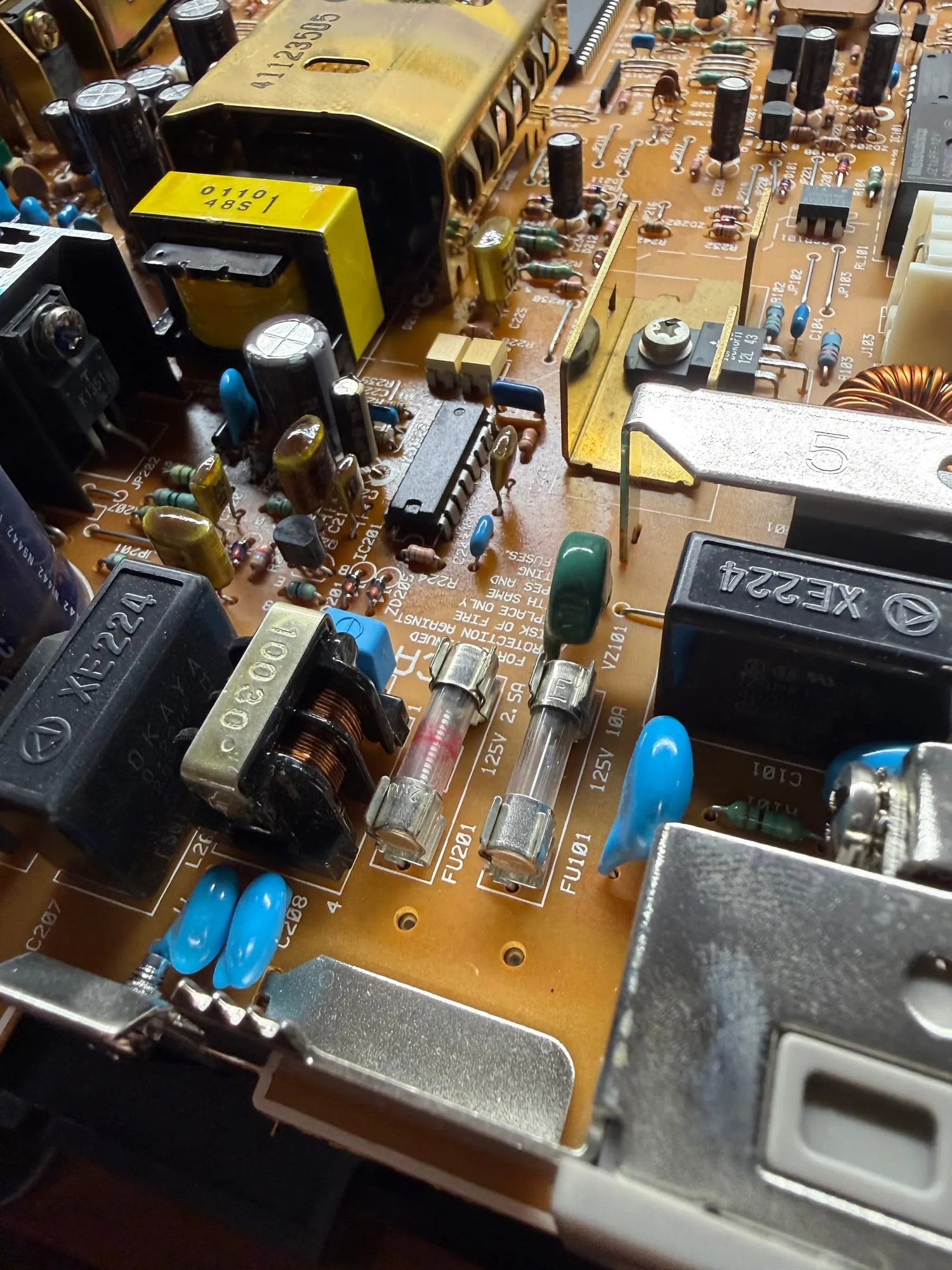
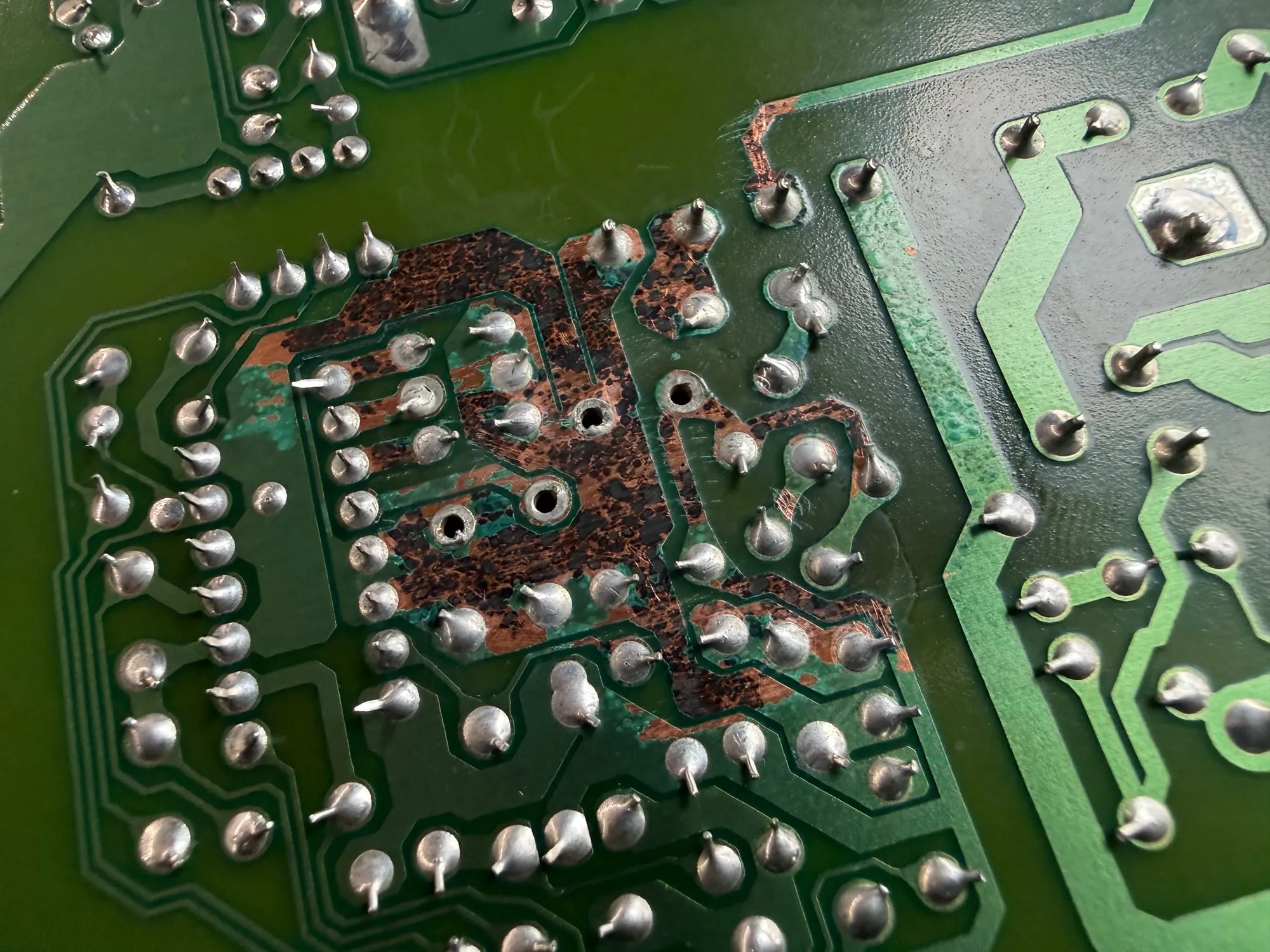
The chip that starts the supply is IC201, and the caps right next to it were the worst. C227 and C217 had leaked, and on the underside of the board the copper around them had gone dark and speckled.
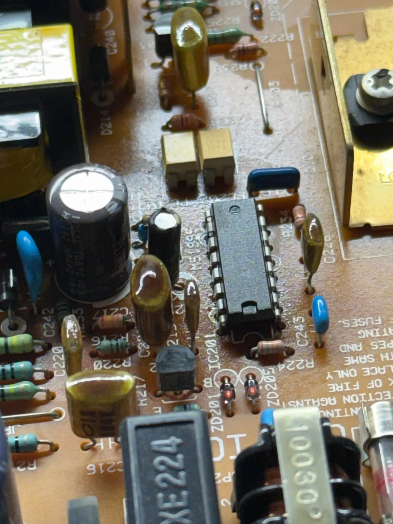
The blue caps near the fuses (C207 and C208) looked crusty too, but they’re ceramic and don’t hold any liquid. The brown stuff on the big solder joints is just old flux.
2. Pull the old caps
I replaced every electrolytic cap on the board except the big 330µF one, which was holding its charge fine. They’re all the same age, and once the iron is hot it isn’t much more work.
Take a few photos before you start so you can check which way each cap went. The stripe on a cap marks its negative leg.
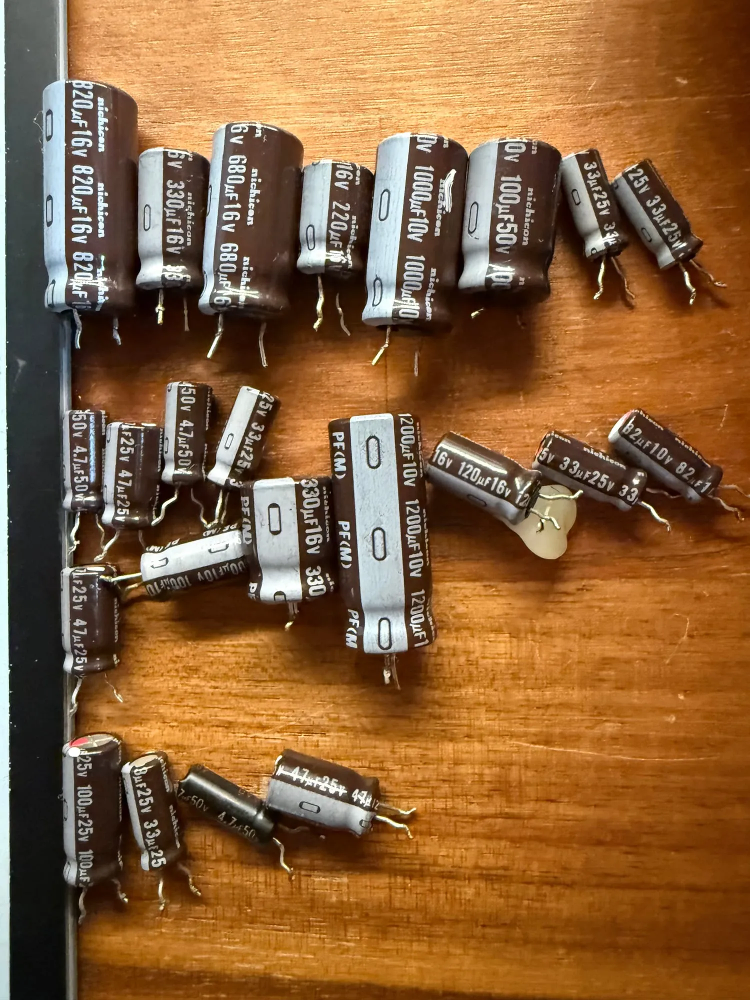
I used my Pinecil and solder wick. I kind of wish I’d had a vacuum desoldering station, but the wick worked pretty well. Pulling all 25 took me about 40 minutes.
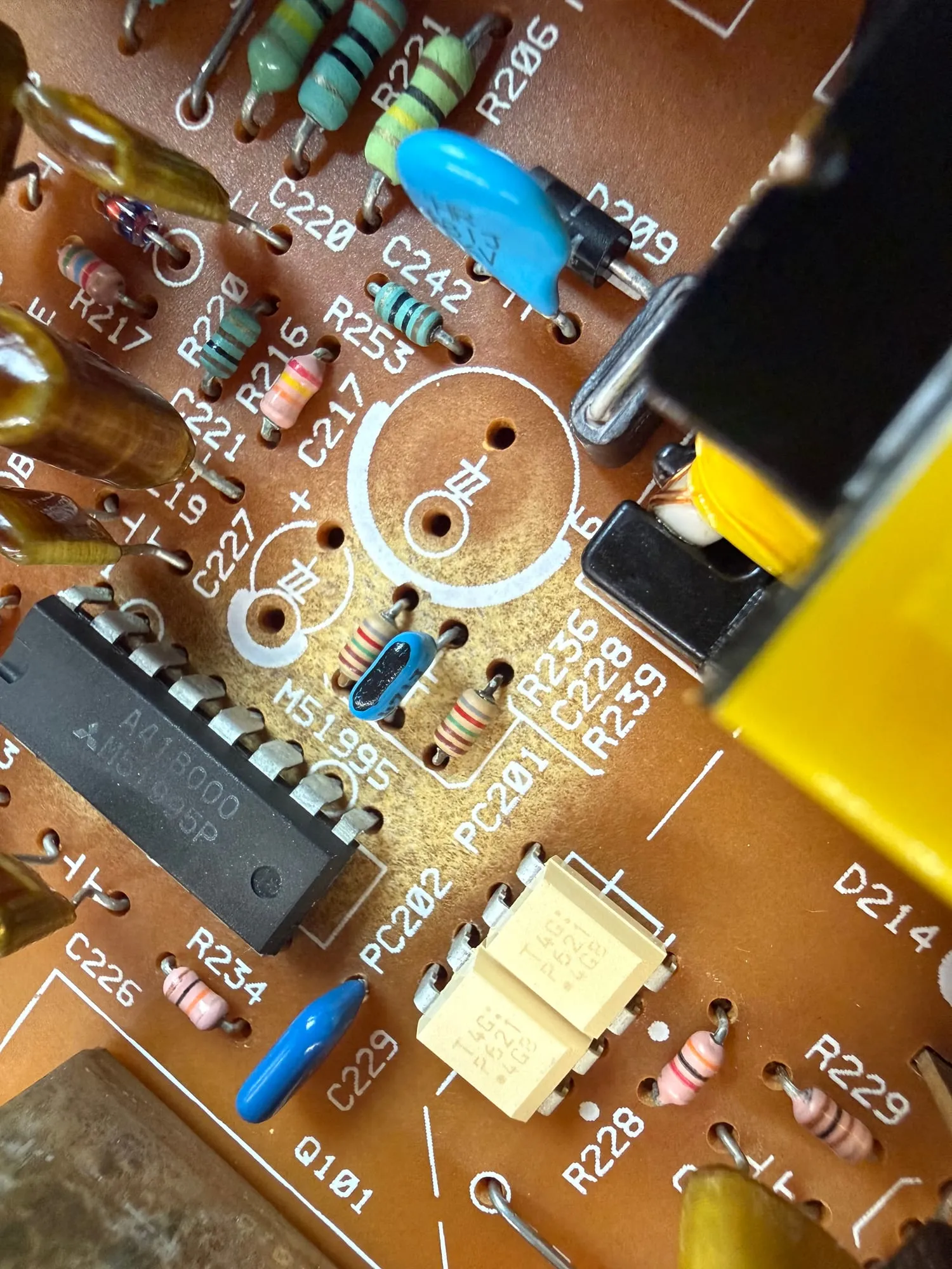
3. Clean the board and fix the traces
I cleaned the whole board with isopropyl alcohol, then scrubbed the stained spots with dish soap and distilled water, rinsed it with alcohol again and blew it dry with compressed air. Then it sat for a couple of days while I waited for the new caps.
On the underside, I scraped the corrosion off the traces with an X-Acto knife, very gently so I didn’t cut into the copper. Then I checked every trace with the meter. All of mine had continuity, so I didn’t need any bodge wires. If one of yours is broken, bridge it with a short piece of thin wire.
Scraping takes the solder mask off along with the corrosion, so I painted new UV-cure solder mask over the bare copper and cured it under a UV light.
4. Fit the new caps
These are the caps I used. This Digi-Key cart has all 25, each line labelled with where it goes on the board. A few are a higher voltage than the originals, which is fine, and C234 was 82µF originally. The 4.7µF caps need their leads bent in a little to fit.
| Position | Value | Digi-Key part |
|---|---|---|
| C109, C223, C224, C230, C418 | 33µF 35V | EEU-EB1V330S |
| C227, C240, C313, C425 | 4.7µF 50V | EEU-FR1H4R7B |
| C413, C414, C415 | 47µF 25V | EEU-FR1E470 |
| C110, C234, C601 | 100µF 25V | EEU-EB1E101S |
| C217 | 100µF 50V | UPW1H101MPD |
| C320 | 120µF 16V | EEU-FS1C121 |
| C417 | 220µF 16V | UPW1C221MPD |
| C205, C245, C246 | 330µF 16V | UPW1C331MPD |
| C416 | 680µF 16V | EEU-FR1C681 |
| C236 | 820µF 16V | UPW1C821MPD |
| C247 | 1000µF 10V | EEU-FS1A102 |
| C215 | 1200µF 16V | EEU-FC1C122 |
Watch the polarity on every one. Putting them back took me less time than pulling the old ones out.
5. Power it up
Mine started right up. Overall the damage was pretty minor, and it could have been a lot worse.
Now it prints from my phone through AirWriter, the AirPrint adapter I’ve been building for old Apple printers.