As an eBay Partner, I may be compensated if you make a purchase.
With summer approaching, we’ve been spending more and more time outside in the yard. We recently upgraded our media center with a Sonos Beam and I wanted to stay in the Sonos ecosystem with other speakers around my house-including outdoors.
My first surprise was that Sonos doesn’t have a battery-powered speaker. I sort of assumed based on the ubiquity of cheap Bluetooth speakers that Sonos would have a high-end version. Nope. Next, I checked the aftermarket for a battery dock or external battery add-on. No dice.
Getting creative
In my search, I found a post by James Callaghan where he added a microUSB port to his Play:1 with a boost converter to run off a standard 5v battery pack. One downside he discovered was the relatively low max volume due to the boost converter stepping down the amperage to get the necessary 24v out of the 5v USB supply.
I had an idea. USB-C Power Delivery is everywhere these days, and can deliver 20v at up to 5a. I did some searching and found a USB-C PD “decoy” board that has a USB-C port and a chip that tricks a PD-compatible charger into thinking it’s charging a device at 20v.

It works perfectly! Now I can bring my Sonos out into the yard with a 26800mAh battery pack and it lasts pretty much all day. Instructions below if you’re interested in making your own!
Instructions
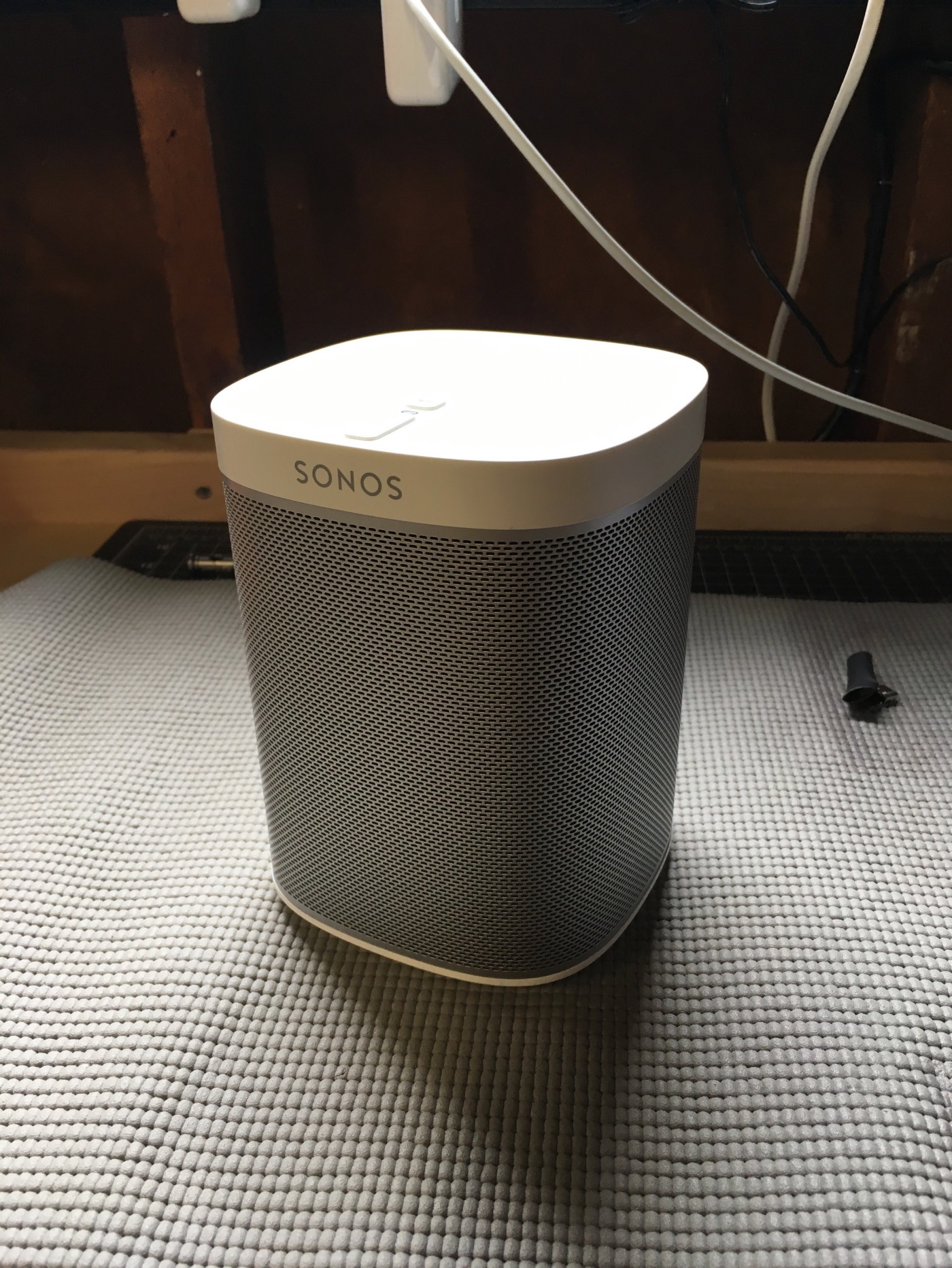
Get yourself a Sonos Play:1 that you want to hack. This will void your warranty! So be careful and take your time. I’m not responsible for bricked Sonoses :)
-
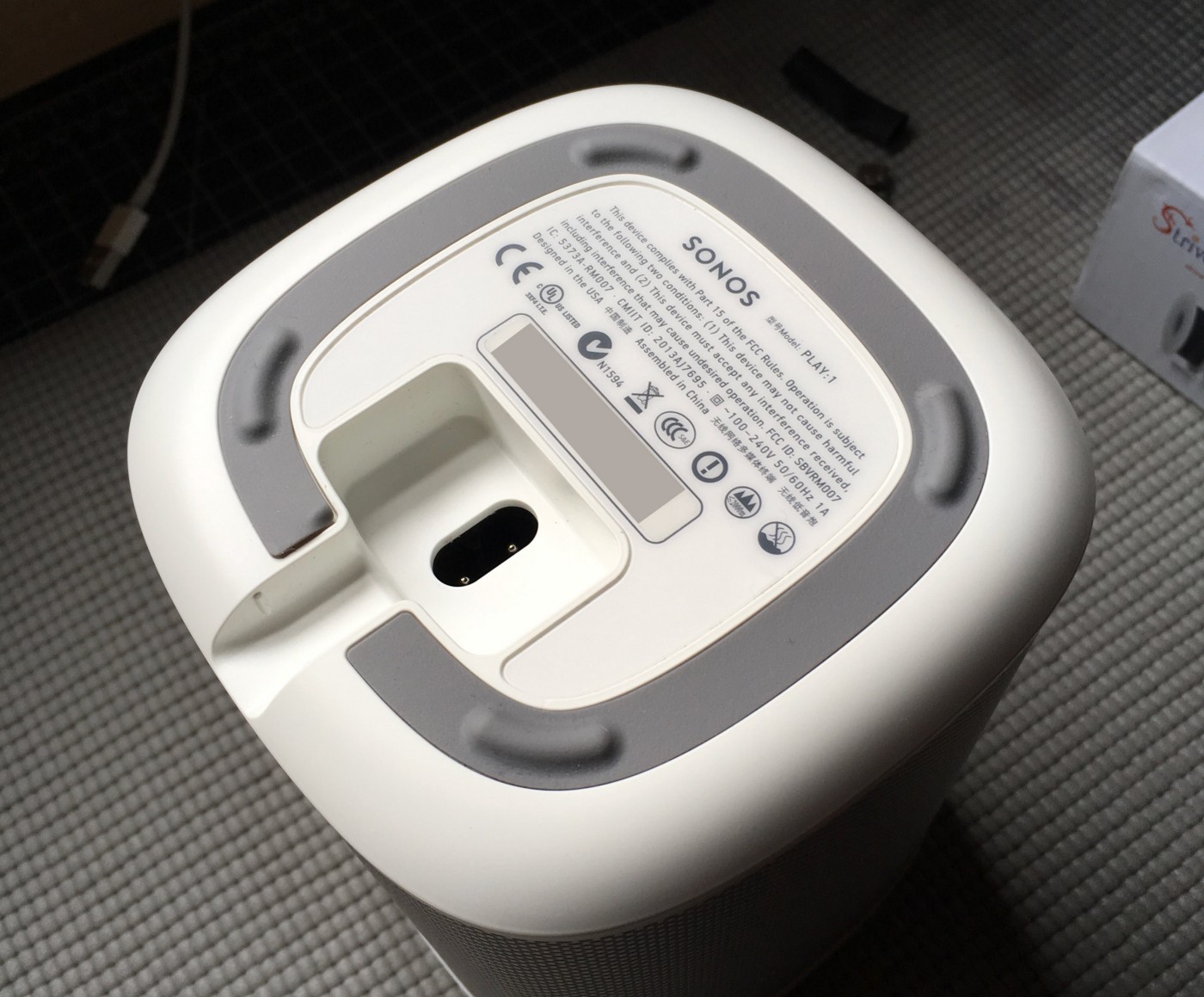
Flip over your Play:1
-
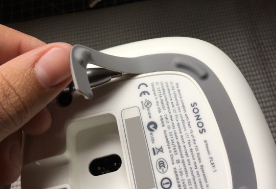
Peel off the rubberized foot strip with a thin screwdriver or spudger. Go slowly to avoid damaging the adhesive. If you do it correctly, it’ll go back on at the end looking brand new.
-
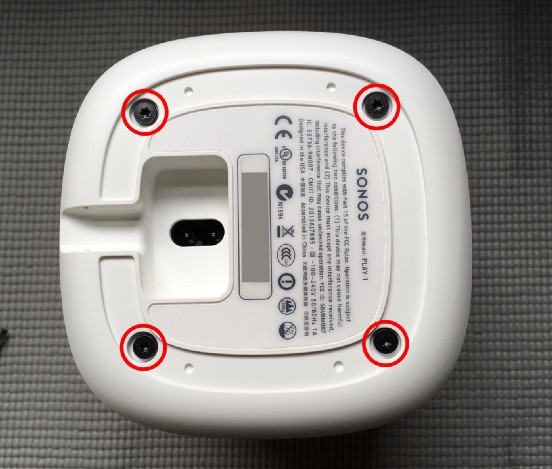
Remove the four Torx #10 screws from the base, then remove the base by lifting straight up.
-
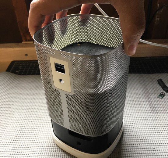
Remove the metal screen by sliding it straight up and off the unit. You may need to squeeze the sides a bit to clear the ethernet port and grounding lug.
-
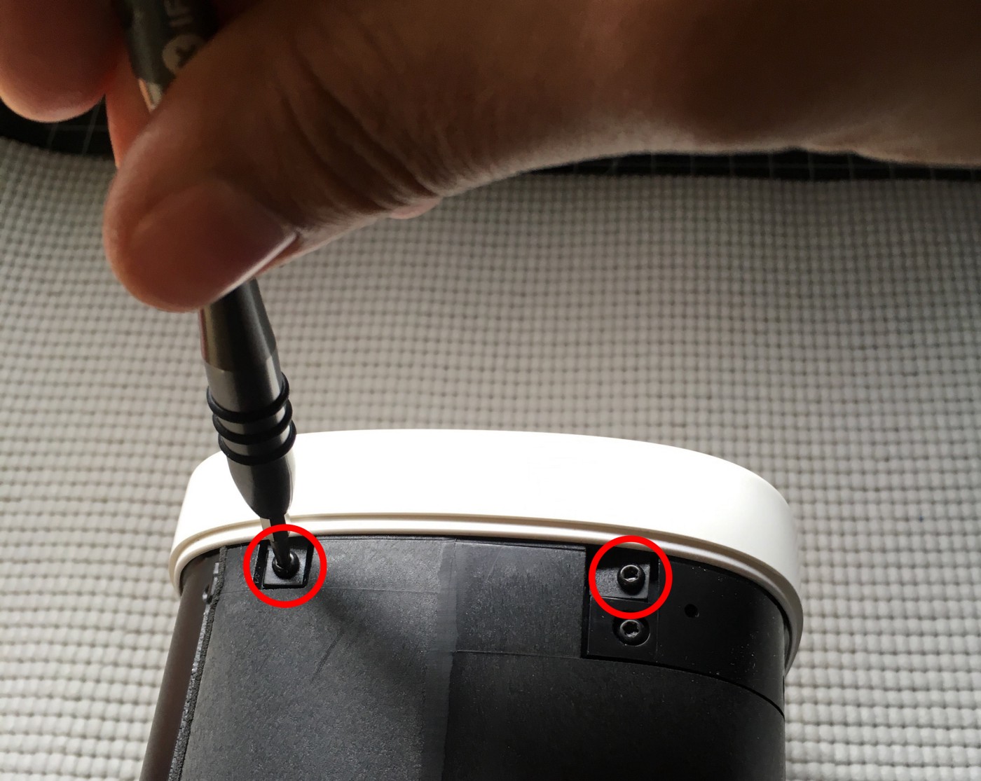
Flip over the unit and remove the four Torx #9 screws from the sides of the top cover.
-
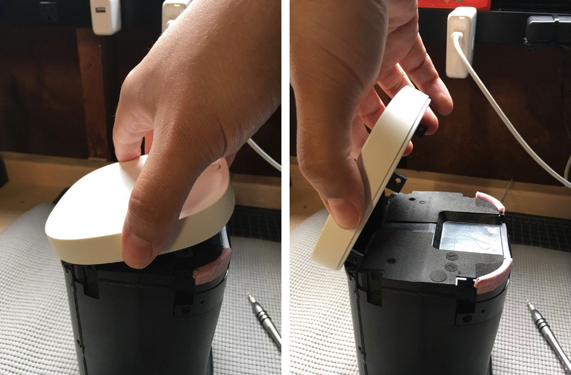
Carefully remove the top cover. It is wedged on tightly with foam and a little bit of adhesive. Don’t yank it off or you might damage the delicate ribbon cable connecting the buttons and indicator light. Once it’s loose, tilt it up towards the back of the device (away from the speaker).
-
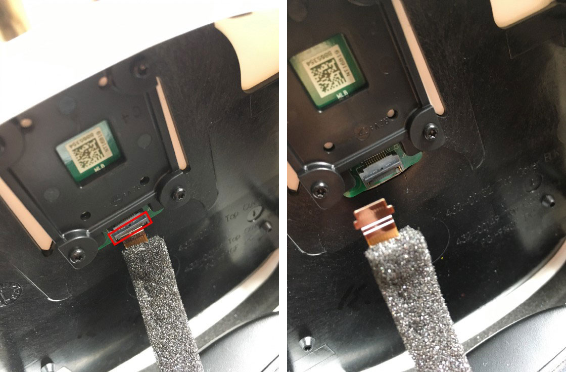
Unlatch the ribbon cable with your finger. There is a small plastic flap holding the cable in place. Swing it open and the cable will fall out. Set the top cover aside.
-
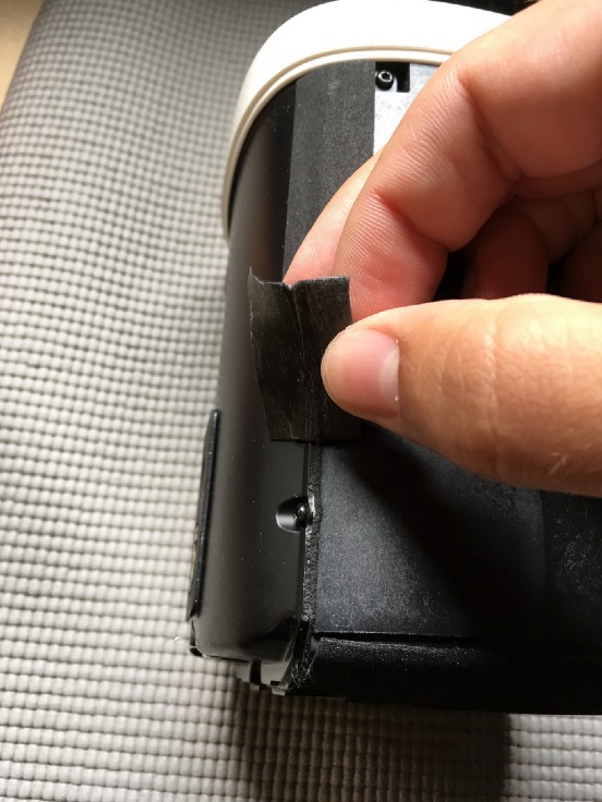
Flip the unit over so that it’s speaker-side down. Gently peel off the foam tape on either side of the rear cover. Go slowly. It’s easy to tear this tape and ruin it, but it is possible to cleanly remove it in one go. Set the strips aside—we’ll reuse them during reassembly. Don’t worry if you tear the tape. You can either piece it back together or replace it with vinyl electrical tape if needed.
-
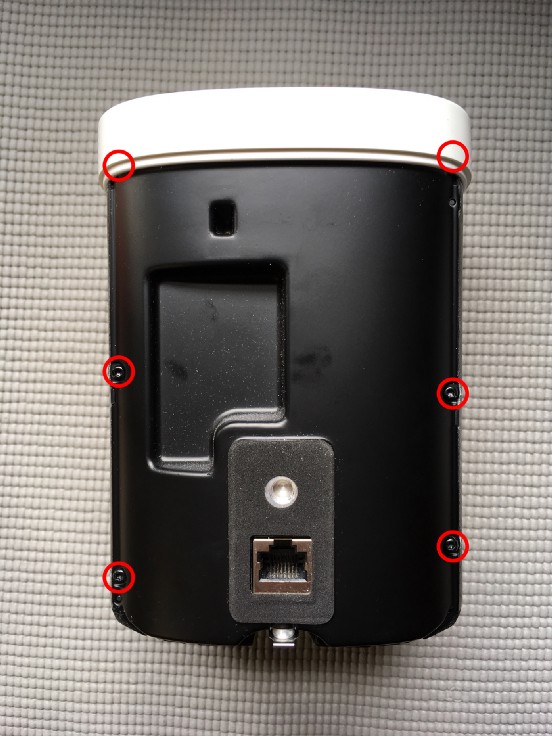
Remove the six Torx #9 screws from the rear cover and gently pry the rear cover away a few mm from the unit. Don’t pull too far—there are cables connecting the two halves that need to be disconnected first.
-
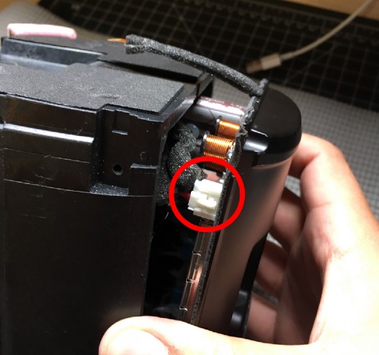
With your fingers, unlatch the speaker cable near the top of the rear cover. Fold the rear cover down so that the bottom edge of the rear cover is resting against the inside of the main unit.
-
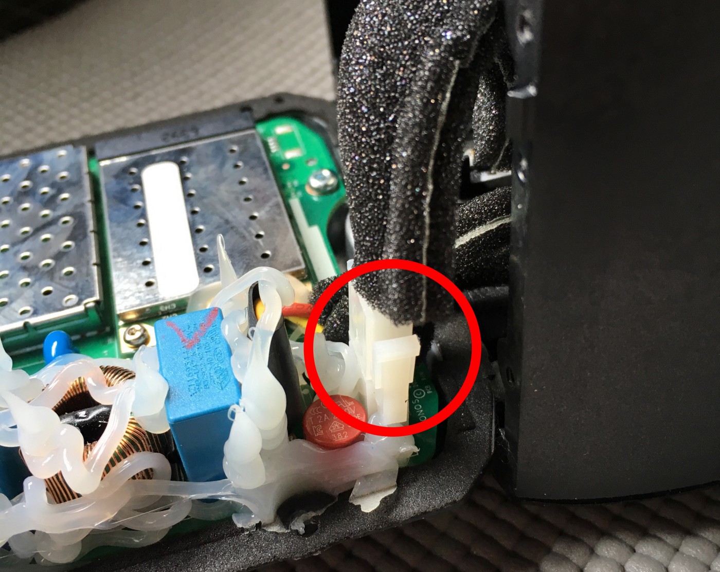
With your fingers, unlatch the power cable near the bottom of the rear cover.
-
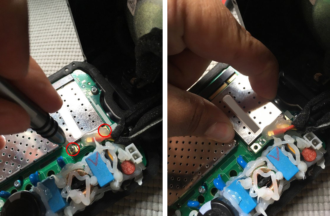
Remove the two Torx #6 screws securing the Wi-Fi card. If the screws are covered with hot glue, carefully cut the glue away first. Pull the Wi-Fi card straight out from the connector to avoid damaging it.
-
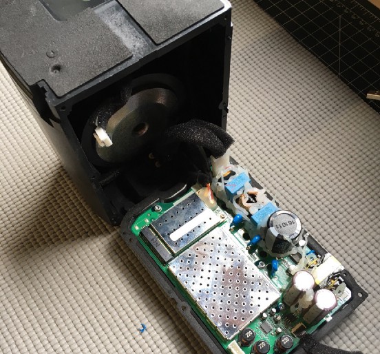
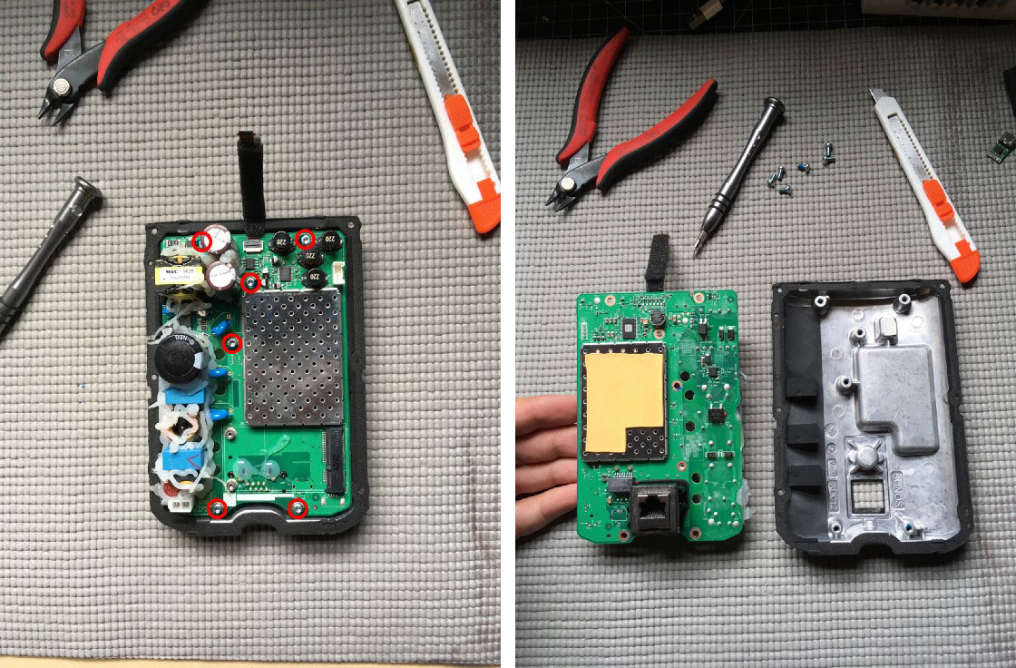
Remove the six Torx #10 screws securing the motherboard to the rear case. Gently pry the motherboard out, being careful not to touch the thermal pad on the rear of the heatsink.
-
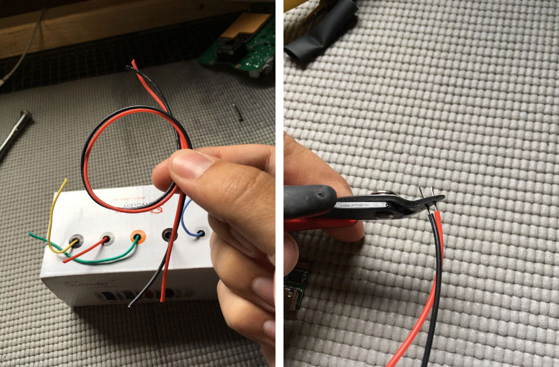
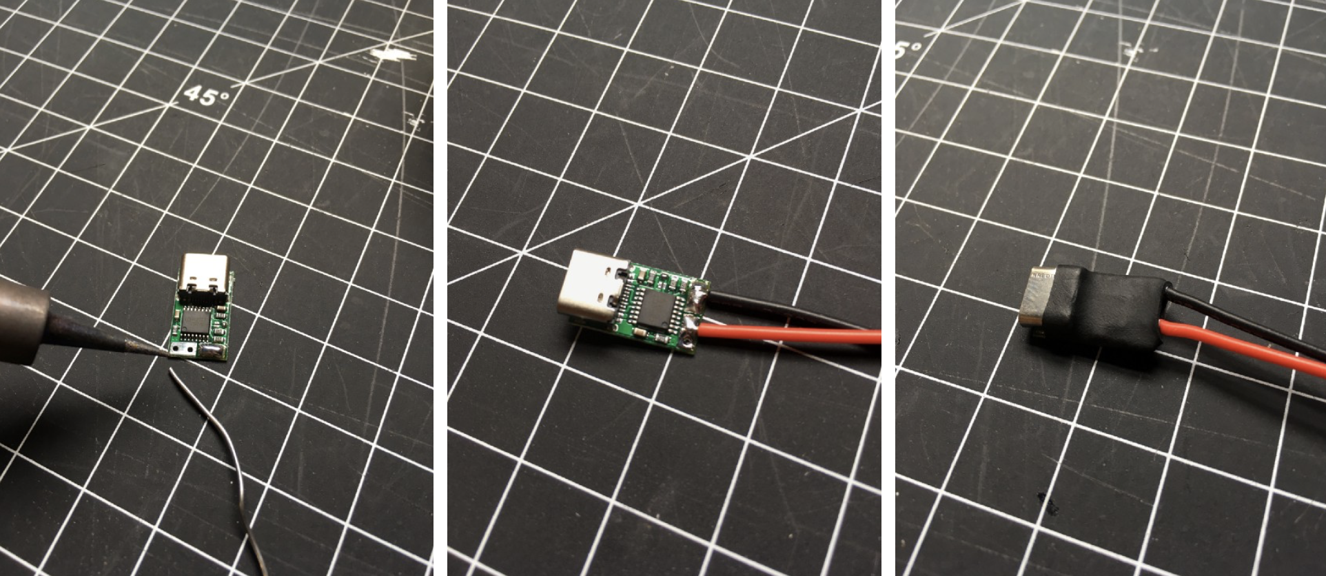
Strip about 5mm off the ends of a 15cm piece of 24awg silicone stranded wire. You can use any kind of wire you like, but I prefer silicone because it’s easy to work with and very flexible. One black (negative) and one red (positive).
-
Flow some solder on the positive and negative pads of the ZYPDS decoy USB-C board, and tin the leads of the silicone wire. Solder them together, then put a small piece of heatshrink tubing over the board and shrink it down.
-
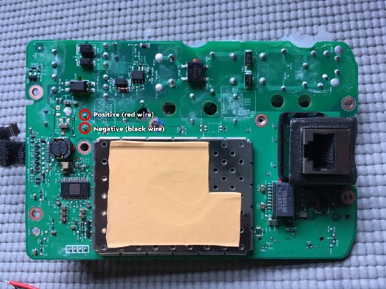
Solder the other ends of your positive and negative wires to the DC output on the back of the motherboard. Run the wires down towards the ethernet jack and secure with electrical tape.
-
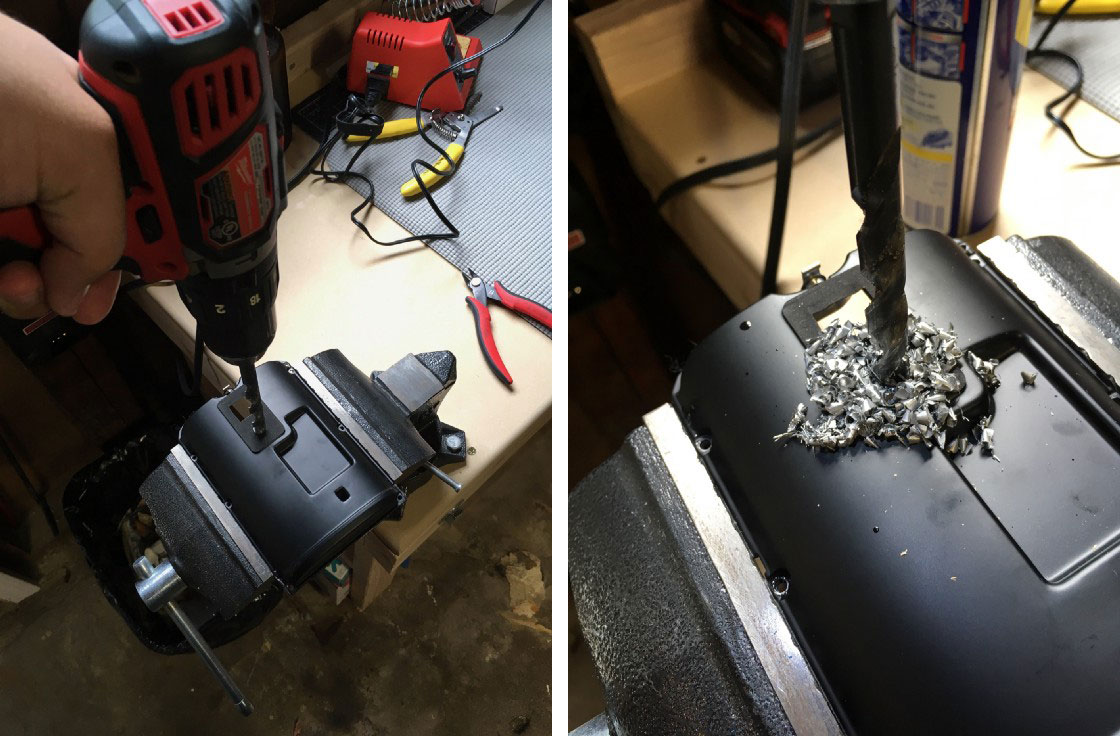
Time to make a hole in the rear case to accommodate the USB-C port. I chose to drill out the mounting terminal since I never mount my Sonos speakers. It’s the perfect size for the USB-C port and has the added bonus of not needing to cut the metal screen. I used a 3/8” wood drill bit with some WD-40 as lubricant. Go slowly! Let gravity do the work. Eventually you’ll break through. Take care to clean up all your chips and the lubricant after you’re done… you don’t want any of the zinc shavings shorting out the electronics!
-
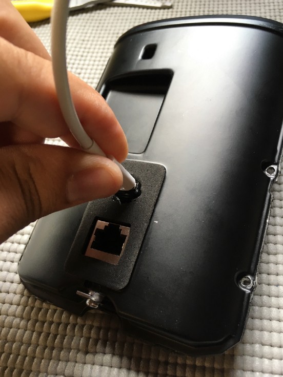
Time for a dry fit. Feed the USB-C connector through the hole you made. If it fits, center the port in your hole using a spare USB-C lead. Place the motherboard back into the rear case to check the clearance. Fill in the gaps around the connector with hot glue from the outside. Once it’s dry, fill in from the inside as well. Cut the excess glue on the outside flush with the foam.
-
Re-assemble the Play:1 following the previous instructions in reverse.
-
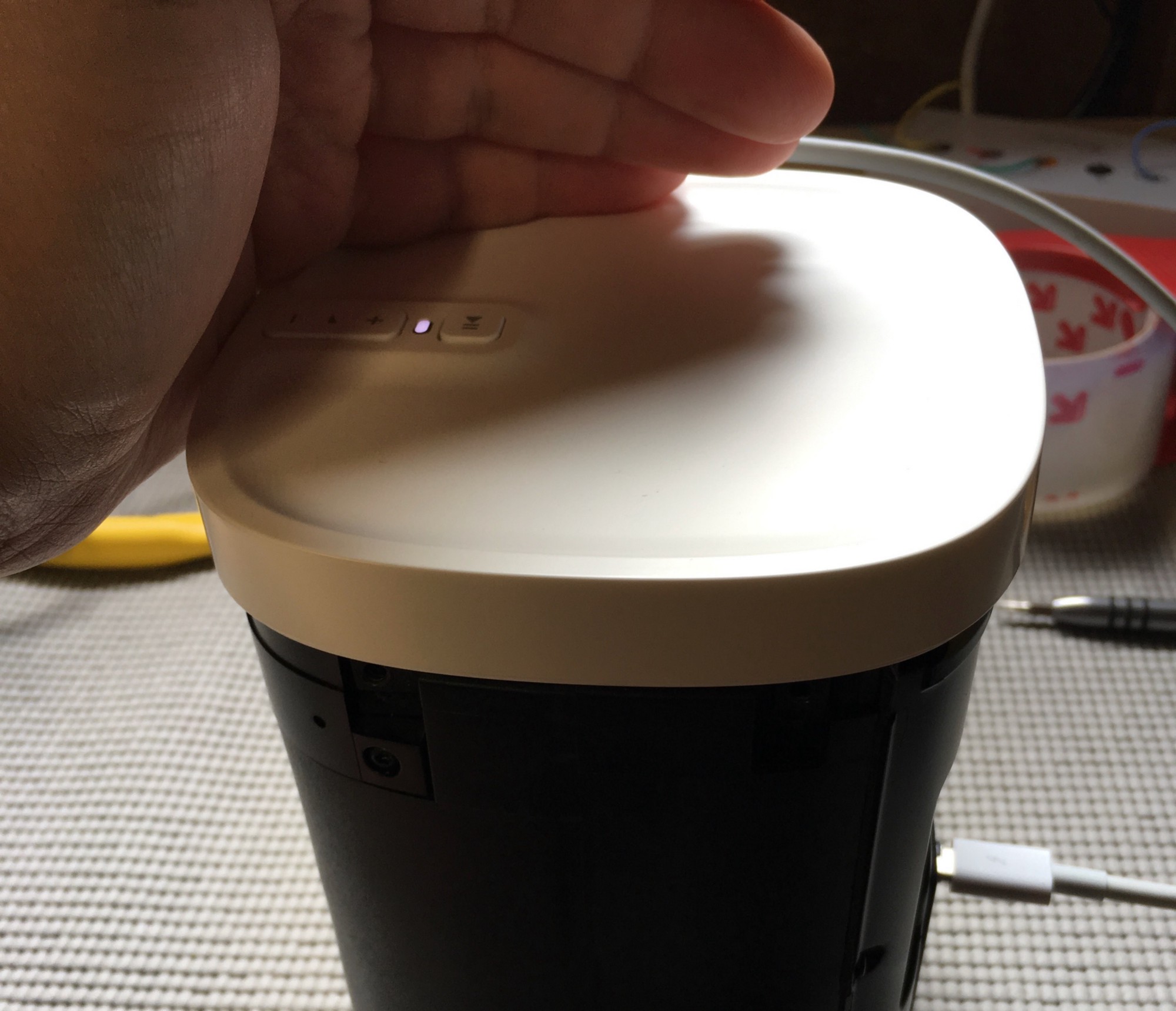
The moment of truth—time to test it out. Re-attach the ribbon cable to the top case and plug in a USB-C power supply. A white light means it’s working!
-
The USB-C port is slightly larger than the mounting hole opening in the plastic. I used a Dremel to widen the hole a bit where the port lined up. It didn’t turn out as clean as I hoped, but fortunately it’s on the back of the device where no one will really see it.
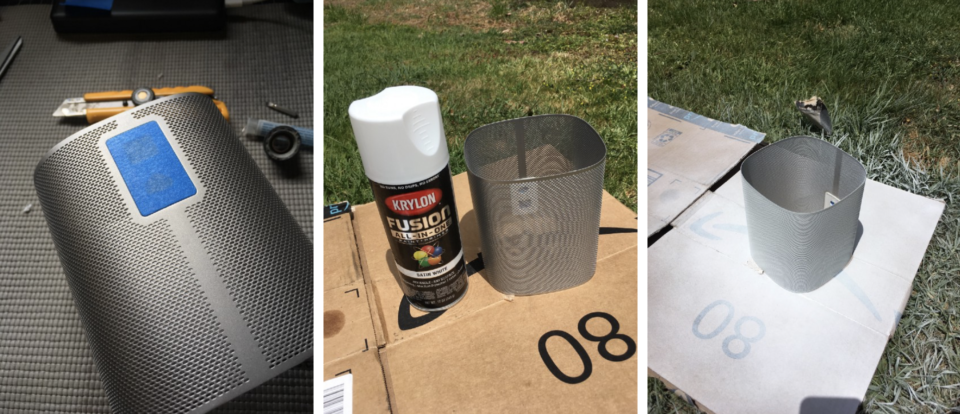
At this point, you’re pretty much done. But I also went a step further by painting the screen white to match the Sonos One in my living room. I used Krylon Fusion all-in-one White for this project and it matches almost perfectly.
Result
I’m very happy with how these turned out (oh, I made two!) They work brilliantly in the yard. I also set up AirConnect on my Synology DS918+ so that they appear as AirPlay devices in iOS! Normally you need the newer Sonos One for that.
The volume gets loud. I was able to turn it up well beyond the maximum comfortable listening volume. USB-C Power Delivery works like a champ!